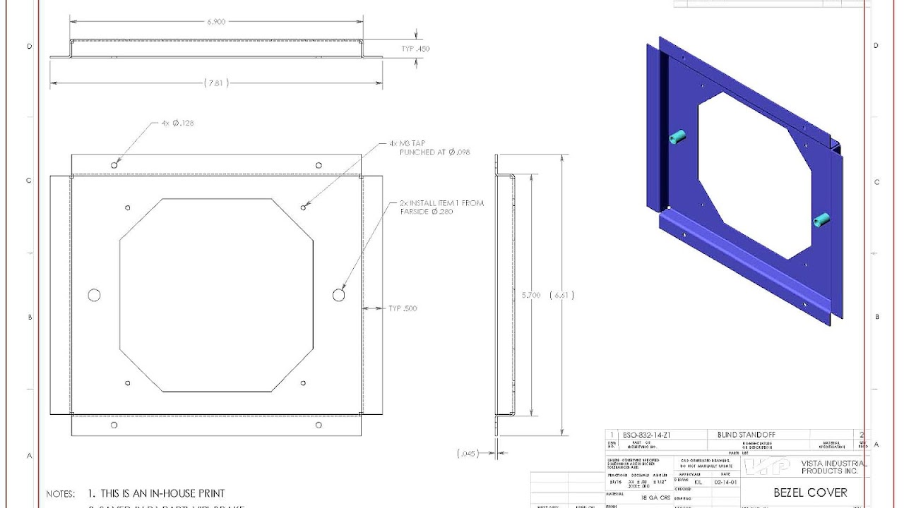
A blueprint is a reproduction of a technical drawing, documenting an architecture or an engineering design, using a contact print process on light-sensitive sheets. Introduced in the 19th century, the process allowed rapid and accurate reproduction of documents used in construction and industry. The blue-print process was characterized by light-colored lines on a blue background, a negative of the original. The process was unable to reproduce color or shades of grey.
Various base materials have been used for blueprints. Paper was a common choice; for more durable prints linen was sometimes used, but with time, the linen prints would shrink slightly. To combat this problem, printing on imitation vellum and, later, polyester film (Mylar) was implemented.
The process has been largely displaced by the diazo whiteprint process and by large-format xerographic photocopiers, so reproduced drawings are usually called "prints" or just "drawings".
The term blueprint is also used less formally to refer to any floor plan (and even more informally, any type of plan).

Maps, Directions, and Place Reviews
The blueprint processes
In 1861, Alphonse Louis Poitevin, a French chemist, found that ferro-gallate in gum is light sensitive. Light turns this to an insoluble permanent blue. A coating of this chemical on a paper or other base may be used to reproduce an image from a translucent document.
The ferro-gallate is coated onto a paper from aqueous solution and dried. The coating is yellow. In darkness, it is stable for up to three days. It is clamped under glass and a light transmitting document in a daylight exposure frame which is similar to a picture frame. The frame is put out into daylight requiring a minute or two under a bright sun or about ten times this under an overcast sky. Where ultra-violet light is transmitted the coating converts to a stable blue or black dye. The image can be seen forming. When a strong image is seen the frame is brought indoors and the unconverted coating, under the original image, is washed away. The paper is then dried.
The result is a copy of the original image with the clear background area rendered dark blue and the image reproduced as a white line. The image is stable. The contact printing process has the advantage that no large-field optical system is required. A further advantage is that the reproduced document will have the same scale as the original. Another quality is that the dark blue background makes it difficult to add new information to the print (such as recording as-built changes); a blueprint cannot easily be altered--depending on the situation, this can be either a strength or a drawback. Since the paper is soaked in liquid during processing, a minor change of scale can occur, and the paper can also become brittle. Engineering drawings often are marked to remind users not to rely on the scale of reproductions.
Other blueprint processes based on photosensitive ferric compounds have been used. The best known is probably a process using ammonium ferric citrate and potassium ferricyanide. In this procedure, a distinctly blue compound is formed and the process is also known as cyanotype. The paper is impregnated with a solution of ammonium ferric citrate and dried. When the paper is illuminated, a photoreaction turns the trivalent (ferric) iron into divalent (ferrous) iron. The image is then developed using a solution of potassium ferricyanide forming insoluble ferroferricyanide (Turnbell's blue identical to Prussian blue) with the divalent iron. Excess ammonium ferric citrate and potassium ferricyanide are then washed away.
This is a simple process for the reproduction of any light transmitting document. Engineers and architects drew their designs on cartridge paper; these were then traced on to tracing paper using India ink for reproduction whenever needed.
Introduction of the blueprint process eliminated the expense of photolithographic reproduction or of hand-tracing of original drawings. By the later 1890s in American architectural offices, a blueprint was one-tenth the cost of a hand-traced reproduction. The blueprint process is still used for special artistic and photographic effects, on paper and fabrics.
How To Read Machining Blueprints Video
Blueprints replaced by whiteprints
Traditional blueprints have largely been replaced by more modern, less expensive printing methods and digital displays. In the early 1940s, cyanotype blueprint began to be supplanted by diazo prints, also known as whiteprints, which have blue lines on a white background; thus these drawings are also called blue-lines or bluelines. Other comparable dye-based prints are known as blacklines.
Diazo prints remain in use in some applications but in many cases have been replaced by xerographic print processes similar to standard copy machine technology using toner on bond paper. More recently, designs created using computer-aided design techniques may be transferred as a digital file directly to a computer printer or plotter; in some applications, paper is avoided altogether and work and analysis is done directly from digital displays. Another common modern method of copying is the use of large-format scanners. These digitize an image which can then be printed with a large-format plotter.
As display technologies have advanced, the use of mobile devices, tablets, for viewing plans has increased significantly among modern construction firms. Software allows users to view and annotate electronic drawing files.
The traditional term "blueprint" has continued to be used informally (usually by non-expert commentators) to refer to each type of image. Practicing engineers, architects, and drafters just call them "drawings" or "prints".
Source of the article : Wikipedia


EmoticonEmoticon